33/11 kV Substation Single Line Diagram (SLD) – Main Components and Working Principle
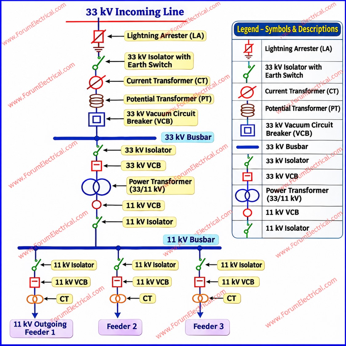
A 33/11 kV distribution substation receives electrical power at 33 kV, steps down the voltage to 11 kV through a power transformer, and distributes it to downstream distribution feeders. The substation incorporates switching, protection, metering, and isolation equipment to ensure reliable power distribution.
1. 33 kV Incoming Section (High-Voltage Side)
-
Lightning Arrester (LA): Protects substation equipment against transient overvoltages caused by lightning and switching surges.
-
Isolator (Disconnector): Provides visible electrical isolation for maintenance. It is operated under no-load conditions unless specifically rated for switching duties.
-
Current Transformer (CT): Steps down primary current for protection relays and metering instruments.
-
Potential Transformer (PT): Provides a reduced voltage signal for metering, monitoring, and protection.
-
Vacuum Circuit Breaker (VCB): Performs normal switching and interrupts fault currents within its rated breaking capacity.
-
33 kV Busbar: Collects and distributes incoming electrical power to the transformer bay and associated circuits.
2. 33/11 kV Power Transformer
-
Steps down the incoming voltage from 33 kV to 11 kV.
-
Transfers electrical power through electromagnetic induction.
-
May incorporate a Buchholz relay for detecting internal faults in oil-filled conservator-type transformers.
-
Includes cooling arrangements, temperature monitoring, and protective devices according to its design.
3. 11 kV Outgoing Distribution Section (Low-Voltage Side)
-
11 kV Busbar: Receives power from the transformer secondary and distributes it to outgoing feeders.
-
11 kV VCBs: Provide switching and fault interruption for individual feeder circuits.
-
CTs and Protection Relays: Monitor feeder current and initiate circuit breaker tripping during detected faults.
-
Isolators: Provide electrical isolation for maintenance.
-
Outgoing 11 kV Feeders: Supply distribution transformers, industrial installations, and downstream electrical loads.
Engineering Note: The actual single-line diagram and equipment sequence depend on the substation configuration, protection philosophy, busbar arrangement, utility requirements, and applicable IEC standards.